
This article was taken from thirdgen.org Written by Robb Millet (bob.millett@lmco.com)
OK, let’s say your swapping out your old drum brake rear axle for a disc version, and you gotta make the brakes work, right? Or you feel like you rear brakes aren’t working as hard as they could and want to change the proportioning from what the engineers at the factory gave you in the stock Proportioning/Combination valve… either way, you’re talking about installing an adjustable brake proportioning valve (PV), the most popular model of which happens to be the infinitely adjustable unit manufactured by Wilwood, and sold thru Summit, Speedway Motors, and J.C. Whitney to name three.
What you’re going to be doing is modifying your front and rear brake circuits, so that the fronts are getting full line pressure always, and the rears will be getting some fraction of that, provided by plumbing the adjustable PV into the chassis line going from the master cylinder (MC) to the rear axle. All the adjustment you’ll be doing will be to the line pressure going to the rear. It’s not a terrifically complicated job, but you do need to be careful.
The most difficult part of the whole deal is getting the stock lines re-flared to mate with the unions on the parts you’ll be installing in place of the stock PV. Stock, all the brakelines, both chassis lines and mastercylinder pipes, terminate in ISO bubble flares. In order to mate with the T fitting and the Wilwood PV, you’ll be cutting off these bubble flares and making new 45 degree female double flares…making the new flares is the most difficult part of this whole deal, beacause the stock lines are of a harder alloy steel than the pre-flared and bendable lines you can buy at the auto parts store…but if you take your time and go carefully, you’ll do ok. Practice helps, so you might find it worthwhile to go to a boneyard and get a handfull of the MC brake pipes that go between the MC and the PV, and practice flaring those first.
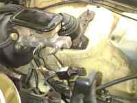
For reference, here’s a picture of the adjustable PV installation in my Z28. Click on the thumbnail for a larger view.
Stuff you’ll need:
Tools:
- Standard Brakeline Double Flaring Kit (get the one out of Summit. It’s the same one I’ve got and has good instructions about creating double flares).
- Tubing Cutter
- Mini Tubing Cutter (for working in the confines of the engine bay).
- Small files and wire brush for cleaning up tubing cuts
- 3/8ths – 7/16ths flare wrench.
- 14mm flare wrench
- ½ open end wrench
Parts:
- Wilwood adjustable PV (without this part, what’s the point?)
- three (3) 3/16ths inverted flare tubing nuts
- two (2) ¼ inverted flare tubing nuts
- one (1) 3/16ths inverted flare female “T” fitting
- two (2) 3/16ths-inverted-male-flare-to-1/4-inverted-female-flare adapters
Notes:
The pipe (exiting the MC) closest to the firewall goes to the front brakes…for that you’ll need the 3/16ths male T junction and the three 3/16ths inverted flare tubing nuts. The wilwood propvalve – which goes in the line to the rear – comes with 2 1/8th NPT fittings that mate it to 3/16ths female Inverted flare fittings. To mate the propvalve to the MC you’ll need the two 3/16ths-male-inverted flare-to-1/4-female-inverted flare adapters, and the two ¼ inverted flare tubing nuts. Of these various adapters, nuts and fittings I’ve listed, BUY EXTRAS!!!! I bought about 3 of everything, and was glad I did.
Procedure
- Step 1: Start out by taking off everything that is in the way of getting at the stock master cylinder (MC) and PV, you’ll need as much room as you can get when you begin flaring the chassis lines.
Disconnect the wire at the connector on the stock PV. Loosen all the various brake line fittings between the MC, PV and chassis lines (one ¼ and one 3/16ths pipe each from the MC to the PV, and one ¼ (rear brakes) and two 3/16ths (front brakes) from the PV to the chassis)
- Step 2: With all the MC/PV fittings fully loosened, remove the brake pipes going from the MC to the PV, notice that the one to the rears is a ¼ inch pipe, and the one to the fronts is 3/16ths, set these aside. Undo the two nuts holding the MC to the vacuum booster cannister and remove the stock PV and throw it away, use it for a paper weight, turn it into a bong bowl, whatever…it ain’t never going back in your car.
- Step 3: The MC is now free too. yank it from it’s mounting on the vacuum booster cannister, take the old MC back to the parts store for your core charge refund :-). Don’t install the new MC yet as youll need the extra space for access while flaring the chassis lines.
NOTE: it helps to do the next few steps in a bench vise, (just remember not to overtighten it and crush the brake pipes!)
- Step 4: Take the ¼ MC-to-PV brake pipe, and with a tubing cutter lop off the bubble flare on the bottom end of the pipe. Cut the flare off as close as you can to the flare (some tubing cutters have a groove in the rollers that the flare will fit into and you can cut the flare off right beneath it).
NOTE: it’s really important to spend the time now to prepare the line for flaring carefully, otherwise you’ll wind up like me, with leaks after my first attempt, and have to do it over like I did.
Clean out the burring on the ID of the pipe (left from the cutting process) and then use a small file to clean up the outer edge of the pipe slightly (it wants a slight chamfer). Wirebrush the outside of the end your going to flare to remove ANY metal shavings, or corrosion, ANYTHING that might contaminate the flare joint.
- Step 5: MAKE SURE YOU PUT THE INVERTED FLARE NUT ON THE PIPE BEFORE FLARING! slide one of the ¼ inverted flare nuts onto the pipe.
- Step 6: Make the 45 deg double flare on the pipe end according to the instructions in the Double flaring tool kit (I have the DF toolkit, same as the one in the Summit catalog, has instructions on how to use it. If you want, by a length of brakeline from the autoparts store and do a few practice flares, or use the extra brake pipes you got at the boneyard.) When you’re done your should have a new rear brake pipe that mates to the MC with the Stock ¼ bubble flare at the top end, and a ¼ 45 deg inverted double flare a the bottom end that mates to one of the ¼-to-3/16ths adapters that will mate to the wilwood PV.
- Step 7: Repeat the above steps 4 thru 6 for the 3/16ths brake pipe that goes to the front. Again, take care to prepare the line well for flaring, don’t allow any contamination, and MAKE SURE YOU PUT THE INVERTED FLARE NUT ON BEFORE FLARING!
NOTE: BEFORE INSERTINGTHE DOUBLE FLARES INTO THE BRASS FITTINGS, CLEAN EVERY BIT OF DIRT OR PARTICLES OFF THE DOUBLE FLARES. ANY CONTAMINATION AT ALL WILL CAUSE A DIVOT INTHE SEALING SURFACE OF THE BRASS FITTING AND CAUSE A LEAK!
- Step 8: Thread the 3/16ths T onto the 45 Deg Inverted Flare now on the bottom end of the MC front line brake pipe (Don’t over tighten the fitting!) Use a ½ open end wrench to hold the fitting, and a 3/8ths flare wrench on the nut.
- Step 9: Thread one of the ¼-to-3/16ths adapters into the 3/16ths fitting on the adj PV inlet..BE REALLY CAREFUL NOT TO OVERTIGHTEN!!! If you break the nut off the fitting in the PV YOU”LL NEVER GET IT OUT without drilling! (don’t ask me how I know this..just look at the top of the PV in my picture.) Thread the other ¼-to-3/16th adapter into the PV outlet. After the adapters are installed in the PV, thread the ¼ MC brake pipe 45 deg double flare into the adapter on the PV inlet and tighten with a open end wrench on the adapter and a 7/16ths flare wrench on the flare nut going in. When you’re tightening the flare nuts into the brass fittings, go slowly, you’ll be able to feel the brass mating surface deforming under the steel pipe. Maybe practice on one of the extra fittings you bought, dont’ worry about deforming the steel line, you won’t. The seal is made by the brass squishing to form to the steel flare. At this point you have two subasseblies: the 3/16ths MC brakepipe with the T fitting on the end, and the ¼ MC brakepipe with the adj. PV attached. There should be a ¼ female inverted flare adapter fitting sticking out the bottom of the PV (should look like what you see in the picture.) Set these aside.
- Step 10: In the engine bay, take the ¼ chassis line, (rear brakes) and wrestle it into a fairly straight up position…you can be a little rough with it, but don’t go crazy. The stock installation has a nice big service loop in it so you”re assured of plenty of length to work with…use a fairly beefy pair of needle nose and strip away about 3 inches of the spiral-wrap wire brake line shielding (This is a pain in the butt, but you have to do it.)
- Step 11: Loop the bubble flare of the ¼ chassis line, same technique as the MC pipe, as close to the flare as you can get, and then carefully prepare the ¼ chassis line for flaring, just like I described in Step 4. Deburr it, clean off ALL corrosion, basically make sure the edge is good and smooth. Again, MAKE SURE YOU SLIDE THE FLARE NUT ON BEFORE FLARING THE TUBE! (if you forget, you’ll have to cut the flare off, but farther down the pipe, beyond where the flaring tool grips the tube, since the tool forms serrations on the outside of the steel line and if you try to flare on these serrations you’ll wind up with a leak.)
- Step 12: Repeat steps 10 and 11 for the two 3/16ths front brake chassis lines. I cannot stress enough taking care to form the double flares carefully. Taking your time here and doing a good careful job of it will pay off when you bolt everything together and tighten all the fittings, and have no leaks. Again let me reassure you, it’s not especially difficult, but it does reward careful work. OK, so now you’ve got the MC brakepipe subbassemblies put together, and the chassis lines are all nicely flared right? You DID remember to put the flare nuts on the lines before flaring? (DOH!) And you cleaned the living bejeezus out of the doublelfare mating surfaces? *rub rub rub* GOOD! now comes the fun part!
- Step 13: Bench bleed the new MC, fill it with juice, and put the cover on. Try to keep it upright :-). Install the new MC onto the studs on the vacuum cannister and tighten that puppy right down. Insert the 3/16ths front MC brakepipe into the port on the MC and tighten the bubble flare nut going into the MC (14mm flare wrench.)
- Step 14: Wrestle the two 3/16ths front brake lines double flared ends into horizontal positions like shown in the picture…again don’t be afraid to make them go where you want, but don’t go crazy…thread the flare nuts into the T ends and tighten them up. Use a ½ open end wrench on the fitting, and a 3/8ths flare wrench on the flare nuts going in. Tightening/seating the steel line flares into the brass fitting rewards a certain technique: Go slow and be aware of the resistance on the flare wrench as you tighten. The resistance to tightening will increase a bit as the brass under the steel line flare begins to deform, and once it’s fully seated, the resistance to tightening goes up quickly.
- Step 15: Thread the ¼ rear MC brake pipe/PV subassy into the port on the MC, and tighten the bubble flare nut (14 mm flare wrench) into the MC…bend the chassis line around to mate with the ¼-to-3/16ths adapter on the outlet of the PV. Tighten with an open end wrench on the adapter, and a 7/16ths flare wrench on the flare nut. Again, go slowly and be aware of the resistence to tightening, feeling for where the flare is fully seated…DO NOT OVERTIGHTEN…the brass fittings are much softer than the steel, and it’s really easy to be ham fisted about it and break/strip them.
- Step 16: Go around again and check the tighteness of all the fittings, making sure the flares are fully seated. This is a very important step..do not skip this!
- Step 17: Fill the MC, clean off all the spillage on the new fittings, and start bleeding the brakes.
- Step 18: Once the brakes are bled, adjust the PV so that the rears are getting full line pressure, and fire up the car. Once the vacuum assist cannister pumps up, HAMMER the brakes (and I mean like two feet on the pedal kinda stuff, where you can feel the firewall flexing and see the top of the MC resevoir moving up an down) while your helper watches the various new fittings for leaks. If any appear, check the tightness of that fitting and see if it’s fully seated. If it continues to leak, that means you DIDN’T GET THE FLARE RIGHT and you’ll have to do the flare over and replace the brass fitting it’s attached to (I only had to redo two.) If there’s no leaks, you’re golden, and have my congrats for a job well done.
Dial-In:
Driving the car now, with the rears getting full line pressure, will cause the rears to lock much before the fronts. Test the car on short hops, preferably on some loose surface (so they’ll lock more easily and not flat spot your tires), and back the adjuster knob out on turn at a time at first, and then by half turns, until the rears lock just after the fronts do.
Yer Done!!! Happy happy, joy joy!
ATGO is not responsible for any damage done to your vehicle by following the above instructions.